
Physical specifications of the RasPiGNSS “Copernicus” module
- Dimensions: 41 x 56mm (excluding SMA connector)
- Weight: 14g
- Antenna connector: SMA female
- Antenna power:
- Power supply: through Raspberry Pi expansion port (P1) or USB connector (configurable via solder jumper)
- Serial communications: through Raspberry Pi expansion port (P1)
- I²C communications: through Raspberry Pi expansion port (P1) and pin header connector
- Status indication: through programmable LEDs and pin header connector
- For detailed electrical and environmental specifications see the NEO-M8T datasheet.
RasPiGNSS “Copernicus” connectors
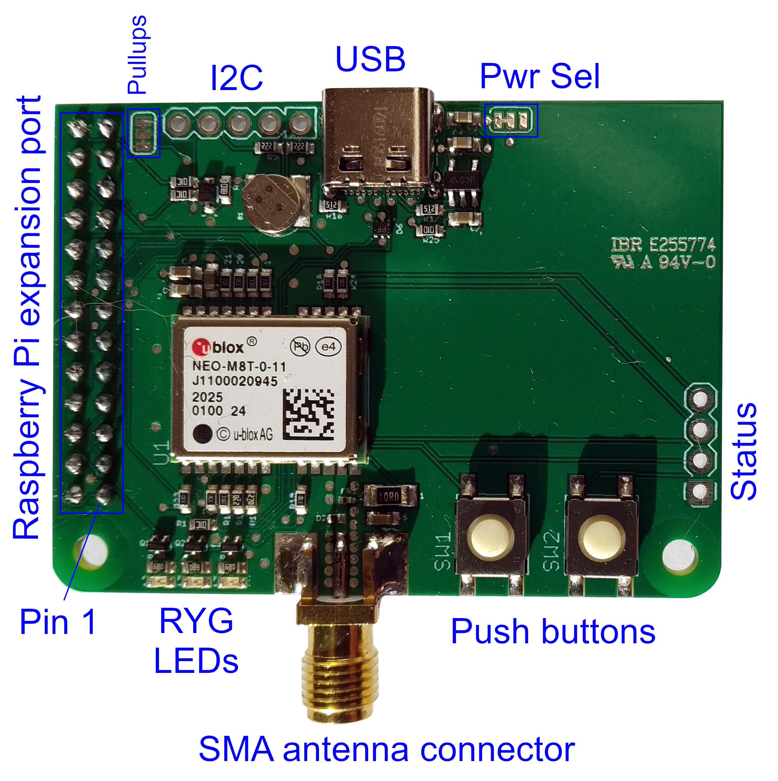
In the image below the connectors and peripheral devices of the RasPiGNSS board have been highlighted in blue. A detailed description of all those connectors is given in the following sections.
USB connector and power selection
The RasPiGNSS “Copernicus” board can either be operated as an add-on module (hardware-on-top, HAT) to the Raspberry Pi minicomputer (the default mode of operation), or as a standalone GNSS receiver using the USB-C connector of the board. In this case, power would also need to be drawn from the USB-C connector. To configure this mode of operation, the solder jumper located to the right of the USB connector in the image above (marked as “Pwr Sel”) needs to be reconfigured: Cut the trace from the middle pad to the left pad, and solder the middle pad to the right pad. This connection is not enabled by default, as the RasPiGNSS board might be damaged, if power is provided at the same time both from the Raspberry Pi and from the USB port, therefore this solder jumper needs to be reconfigured to the desired operation mode.
Note: Any improper hardware modification will void warranty of the RasPiGNSS board! Please contact us if you want to have this modification done prior to shipping the RasPiGNSS.
Note: In the default (unmodified) power selection jumper configuration you may connect a USB cable while the RasPiGNSS board is powered from the Raspberry Pi, e.g. for updating GNSS chip firmware over USB. This is possible since the RasPiGNSS doesn’t draw power from the USB port, yet USB communications will be enabled when plugging in a USB connector.
RasPiGNSS expansion port (P1) connections
| P1 Pin | GPIO | Symbol | Description |
|---|---|---|---|
| P1-1 | +3.3V | Power supply to the NEO-M8T | |
| P1-2 | +5V | Analog and digital power supply, not used by the NEO-M8T | |
| P1-4 | +5V | Analog and digital power supply, not used by the NEO-M8T | |
| P1-6 | GND | Ground | |
| P1-7 | GPIO4 | SW1 | Tactile switch 1 |
| P1-8 | GPIO14 | RX1 | Serial receive of the NEO-M8T, RasPi TXD0 |
| P1-10 | GPIO15 | TX1 | Serial transmit of the NEO-M8T, RasPi RXD0 |
| P1-11 | GPIO17 | SW2 | Tactile switch 2 |
| P1-12 | GPIO18 | RST | Reset pin of NEO-M8T (active low) |
| P1-13 | GPIO27 | TIMEPULSE | 1pps time pulse signal of the NEO-M8T |
| P1-15 | GPIO22 | LED1 | Red indicator LED |
| P1-16 | GPIO23 | LED2 | Yellow indicator LED |
| P1-18 | GPIO24 | LED3 | Green indicator LED |
| P1-19 | GPIO10 | EXTINT0 | External interrupt 0 input of NEO-M8T |
Note: LEDs or switches are not controlled by the NV08C, all I/Os are fully programmable from the RasPi, with the exception of the YELLOW LED, which is controlled by the TIMEPULSE signal of the NEO-M8T by default. Configure pin 16 as output to disable this behaviour and control the LED from the Raspberry Pi. All LEDs are standard 20mA types and are driven from the RasPi via a MOSFET. Configure pins 15, 16, and 18 as outputs and set them high to switch them on. All switches are directly wired to ground. Enable pullups on pins 7, and 11, and do debouncing in software to read them correctly.
I2C connector
The I2C connector provides access to the Raspberry Pi’s I2C-1 bus.
| I2C pin | P1 pin | GPIO | Symbol | Description |
|---|---|---|---|---|
| I2C1 | P1-5 | GPIO3 | SCL1 | I2C clock |
| I2C2 | P1-3 | GPIO2 | SDA1 | I2C data |
| I2C3 | P1-6 | – | GND | Ground |
| I2C4 | P1-1 | – | +3V3 | +3.3V power supply |
| I2C5 | P1-2, P1-4 | – | +5V | +5V power supply |
Note that all I2C signals (
SCL1,SDA1) have +3.3V logic levels. Connecting to a device with +5V logic levels may damage your Raspberry Pi! TheI2C5+5V pin is provided for convenience only, e.g. for devices providing an internal voltage regulator (as some Pololu IMUs do). There are two on-board 2.2 kΩ pull-up resistors for SDA and SCL of the I2C bus, which can be disabled by cutting the solder bridges located between I²C connector and the expansion port on the board (marked as “Pullups” in the image above).
Note: Any improper hardware modification will void warranty of the RasPiGNSS board! Please contact us if you want to have this modification done prior to shipping the RasPiGNSS.
Status connector
The RasPiGNSS “Copernicus” is equipped with a status port connector which features the following pinout:
| Status port pin | Symbol | Description |
|---|---|---|
| 1 | GND | Ground |
| 2 | TIMEPULSE | Timepulse output of the NEO-M8T |
| 3 | EXTINT1 | External interrupt 1 input of the NEO-M8T |
| 4 | LNA_EN | LNA enable output of the NEO-M8T |
Note: All signals of the status connector use +3.3V logic levels. Using voltage levels above +3.3V may permanently damage the RasPiGNSS board!