Prerequisites
Prior to installing the RasPiGNSS make sure you have:
- A Raspberry Pi model A, B, A+, B+, Zero, Zero W, model 2, or model 3 or 4 (either one will fit).
- The latest Raspberry Pi OS (previously “Raspbian”) image from the Raspberry Pi Foundation download page. Depending on your intended application you may want to obtain the “lite” version of the OS without a desktop environment, or the full version including the “Pixel” desktop environment.
- A suitable power supply for the Raspberry Pi delivering at least 0.3 amps more than the minimum specification released by the Raspberry Pi foundation for your specific Raspberry Pi model.
- A RasPiGNSS module.
- A decent GNSS antenna whose power consumption and GNSS receive frequency specifications match the respective RasPiGNSS module. For best results we recommend quality antennas like the ones from Tallysman, especially the ones tested with the RasPiGNSS boards, which you may find in the GNSS antenna section. According to our tests these are known to deliver excellent performance when used with the RasPiGNSS expansion boards.
Installing the hardware
- Make sure your Raspberry Pi is powered off and the USB power cord removed. Never try to assemble the RasPiGNSS module when power is applied to the Rasberry Pi!
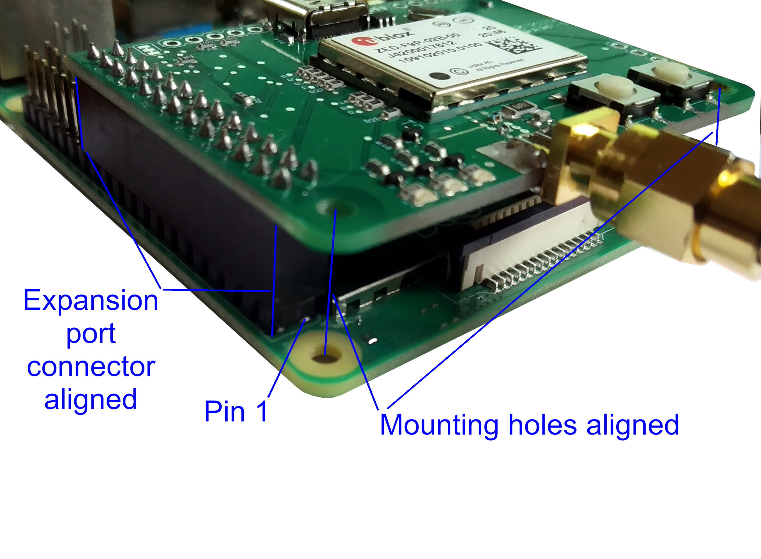
- Carefully mount the RasPiGNSS expansion board on the Raspberry Pi’s P1 expansion port, precisely aligning all pins with the respective holes on the RasPiGNSS connector as shown in the picture to the right. Do not exert excessive force as you may bend or break pins, voiding your warranty on both the Raspberry Pi and the RasPiGNSS expansion board! Take utmost care to avoid misalignment of the pins, as applying power to a misaligned RasPiGNSS will definitely kill your Raspberry Pi and/or the RasPiGNSS expansion board!
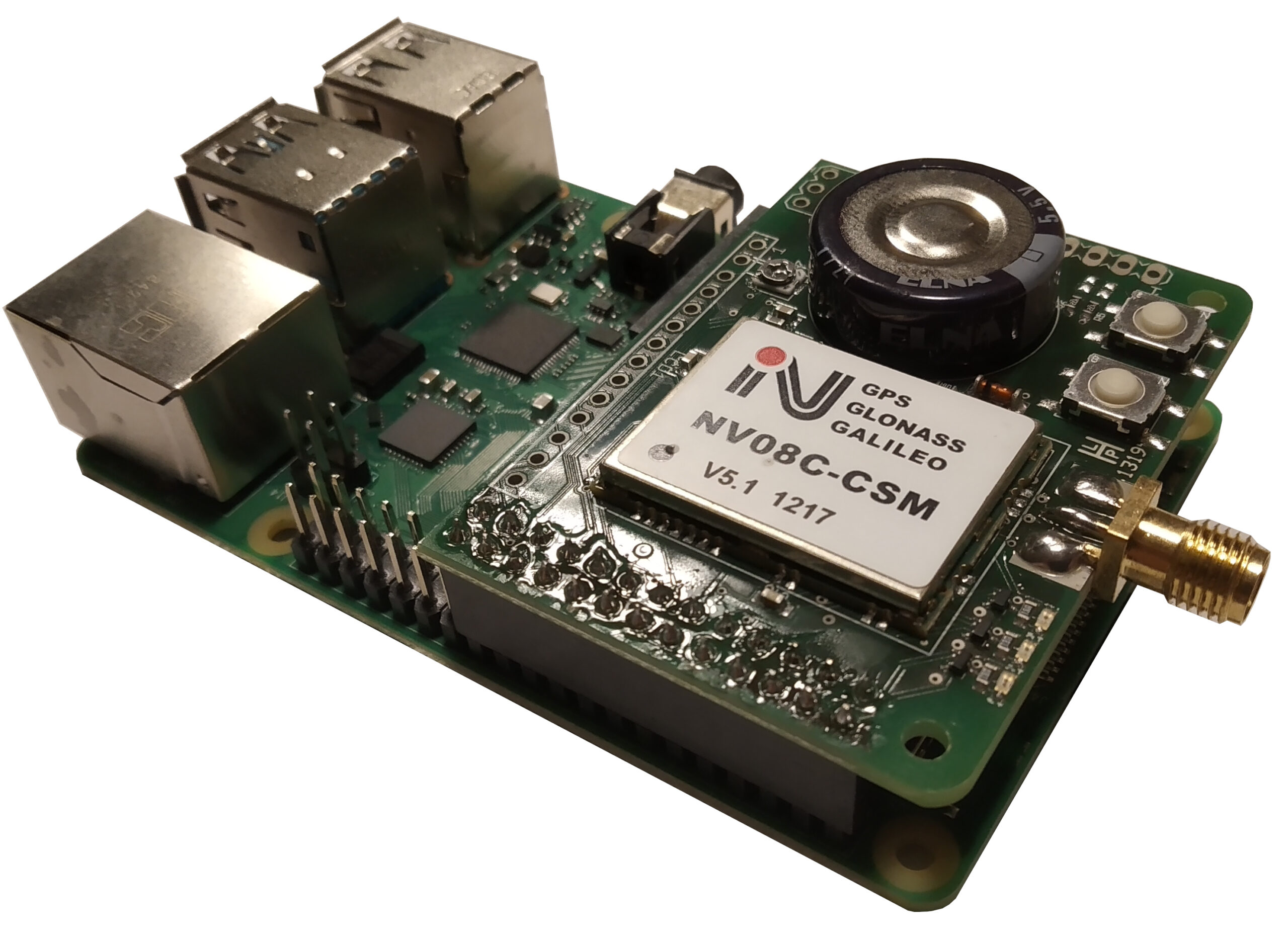
Note: On Raspberry Pi models which feature a 40-pin expansion port (1A+, 1B+, 0, 2, 3, 4), the RasPiGNSS needs to be mounted on the first 26 pins, which are electrically compatible to the earlier models 1A and 1B. The first 26 pins on the new models are the ones starting right beside the power and activity LEDs. You can see how it needs to be mounted on a Raspberry Pi model with a 40-pin connector in the image above. Note that when mounted properly, the mounting holes of the Raspberry Pi and the RasPiGNSS module align properly.
Note: The Raspbian images from 2014-09-09-wheezy-raspbian.img onwards enable pulldowns on the GPIOs and therefore the RasPiGNSS RESET pin (P1 pin 12, GPIO 18) by default. This keeps the NV08C-CSM always in a RESET state, and the board seems “dead”. In order to make the RESET pin work as intended you first have to disable the pulldowns with
rpio pulloff 12prior to using the device. This restores normal behaviour of this pin as was the case with the previous 2014-06-20-wheezy-raspbian.img. All tools mentioned below have been updated to reflect this firmware change, and when installed will modify/boot/config.txtaccordingly to initialize all I/O pins correctly for the RasPiGNSS.
Installing the software
- Install the latest Raspberry Pi (Raspbian) OS version from the Raspberry Pi foundation download page (see above).
- Ensure that in
/boot/config.txtthe UART clock is set to 6 MHz. Insert the lineinit_uart_clock=6000000in/boot/config.txtand reboot. Otherwise you cannot switch the RasPiGNSS to higher baud rates like 230400 baud on the UART, which are necessary to receive raw satellite measurement data. See https://www.raspberrypi.org/documentation/configuration/config-txt/boot.md for details! - Make absolutely sure that your
/dev/ttyAMA0serial port is unused! (see Preventing Linux from using the serial port on the eLinux wiki) . See note below for Raspbian “Jessie” and above!- ensure there are no references to
/dev/ttyAMA0in/boot/cmdline.txt. - ensure there are no references to
/dev/ttyAMA0in/etc/inittab - Reboot!
- ensure there are no references to
- For the RasPiGNSS “Aldebaran”: Download and install the rpgtools. (Note: Privileges are required to access
/dev/ttyAMA0, so add the user under which you’re executing those scripts to the ‘dialout’ group or execute them with root privileges. These tools are provided under a GNU public license.nvsmodeswitches serial port parameters and NV08C operating modesnvsfwflashes new firmware onto the NV08C; Note: Packagelrzszrequired (sudo apt-get install lrzsz)nvsctlfor intialising and controlling the NV08Cnmeacmdissues a NMEA command to the NV08C, see NMEA protocol specificationbinrcmdissues a BINR command to the NV08C, see BINR protocol specificationrpiois a generic tool to read and set the RasPi’s GPIO ports; Note: Device::BCM2835 module from CPAN required. For the Pi2 use at least version 1.39 of Mike McCauley’s bcm2835 library. For the Pi4 use at least version 1.60. For convenience you may download a compiled and packaged Debian package of this library here.nmeaparsehelps to get an overview of the satellites in view and used for a solution in NMEA mode. Remember to switch to NMEA mode withnvsmode nmeabefore using this command! You can find a more detailed description of this command in the FAQ.
- For the RasPiGNSS “Betelgeuse” and “Copernicus”: Download and install the ubxtools. Note: Privileges are required to access
/dev/ttyAMA0, so add the user under which you’re executing those scripts to the ‘dialout’ group or execute them with root privileges. These tools are provided under a GNU public license.ubxctlfor initialising and controlling the u-blox GNSS chipnmeacmdissues a NMEA command to the u-blox GNSS chip (see the UBX interface description of the respective u-blox GNSS chip)ubxcmdissues a UBX command to the u-blox GNSS chip (see the UBX interface description of the respective u-blox GNSS chip)rpiois a generic tool to read and set the RasPi’s GPIO ports; Note: Device::BCM2835 module from CPAN required. For the Pi2 use at least version 1.39 of Mike McCauley’s bcm2835 library. For the Pi4 use at least version 1.60. For convenience you may download a compiled and packaged Debian package of this library here.ubxnmeaparsehelps to get an overview of the satellites in view and used for a solution in NMEA mode. Remember that the NMEA protocol with a standard set of messages (RMC, VTG, GGA, GSA, GSV, GLL) have to be enabled before using this command! You can find a more detailed description of this command in the FAQ.
Note: Most of the tools need access to the Raspberry Pi GPIO ports and therefore to the
/dev/memspecial device, which needs root privileges to be accessed. So either execute those tools as root, usesudo sometoolor set the toolssetuidbit usingchmod ug+s sometool. Although newer releases of the Raspbian operating system support unprivileged GPIO access, this is not sufficient for the RasPiGNSS, as it uses the serial connection as well, therefore using root privileges with therpgtoolsis mandatory.
Note for Debian “Jessie” and later: In
/boot/cmdline.txtthere is no reference to/dev/ttyAMA0, this is calledconsole=serial0,115200– remove that. Also, with the switch fromupstartto thesystemdinit system,/etc/inittabhas vanished. In order to disable agettyprocess on/dev/ttyAMA0run the commandssudo systemctl stop serial-getty@ttyAMA0.serviceandsudo systemctl disable serial-getty@ttyAMA0.service.
Note: On the Pi3, the Pi4, and the ‘W’ models of the Pi Zero (Zero W, and Zero WH) there has been a hardware change: The previous PL011 UART
/dev/ttyAMA0is now used by the Bluetooth chip. The pins used by the RasPiGNSS for serial communication with the GNSS chip are now mapped to/dev/ttyS0mini-UART. This mini-UART, however, does not have its own clock generator, but uses the CPU clock. CPU clock scaling due to undervoltage or heat therefore causes baud rate glitches that lead to transmission errors. Therefore I strongly discourage use of the/dev/ttyS0port for use with the RasPiGNSS. Fortunately there’s a device tree overlay namedminiuart-bt(formerlypi3-miniuart-bt) that restores the old behaviour, and remaps/dev/ttyAMA0to the GPIO pins used by the RasPiGNSS, forcing the Bluetooth chip to use/dev/ttyS0(Bluetooth my not work then). For this to work, insertdtoverlay=miniuart-btinto your/boot/config.txt. Look up the details in the Raspberry Pi forums.
Note: On the Pi3 with the latest Raspbian Jessie release (from 2016-05-27) you need to manually re-enable the UART, because it will be switched off by default now. Put
enable_uart=1into/boot/config.txtto re-enable the UART, otherwise/dev/ttyAMA0will be gone.
Note: On the Pi4 make sure to use the latest
libbcm2835library (at least version 1.60). Due to the new SOC used on the Pi4, previous versions of the library will not work.
Configuring the LEDs and Push-Buttons
The LEDs and push-buttons are connected to regular GPIO pins on the Raspberry Pi P1 expansion port, and may be controlled with any suitable GPIO support library like the libbcm2835 or the WiringPi library. The rpio utility is included for that purpose that simplifies GPIO handling significantly; however you have to install the Device::BCM2835 Perl module from CPAN first. To switch all LEDs on simultaneously use:
# rpio -v hi out 15 16 18This switches pins 15, 16, and 18 to output mode and sets them to a high level thus turning on the LEDs. To switch them off again use:
# rpio -v lo 15 16 18The pins still remain configered as outputs after this command. To configure pins as input, enable pullups, and read their pin status use:
# rpio -v in pullup read 7 11This configures pins 7, and 11 as inputs, enables pull-up resistors on them, and reads their pin status, thus querying if any of the tactile switches have been actuated.
Note: Depending on the RasPiGNSS model, some of the LEDs may have default functions directly controlled by the GNSS chip used by the respective model. These default functions will take effect of the respective I/O pins are left unconfigured or explicitly set to input mode:
– Aldebaran: No default functions, all LEDs off even when pins are switched to input mode.
– Betelgeuse: The RED LED is connected to GEOFENCE_STAT signal by default, i.e. is ON by default, when no geofences are configured and geofence logic is not inverted. Please refer to the ZED-F9P interface description for configuring geofencing. The YELLOW LED is connected to the TIMEPULSE signal, therefore will blink once a second on startup if left unconfigured. The GREEN LED is connected to the inverted RTK_STAT signal by default, i.e. is OFF by default, blinks when RTCM correction data is received, and is ON when an RTK fix has been achieved. See the ZED-F9P interface description for configuring RTK status indication. Configuring the LED pins as output makes them controllable from the Raspberry Pi.
– Copernicus: The RED and GREEN LEDs have no default function and may be directly controlled from the Raspberry Pi. The YELLOW LED is connected to the TIMEPULSE signal and will blink once a second if left unconfigured. Configuring the YELLOW LED pin 17 as output to control this LED from the Raspberry Pi.